Valve CAD drawings are a critical component in the design and manufacturing process of valves. These detailed technical drawings provide engineers and manufacturers with the necessary information to ensure the proper functioning and assembly of valves. In this article, we will explore the importance of Valve CAD drawings, their components, and how they contribute to the efficiency and quality of valve manufacturing.
**Introduction**
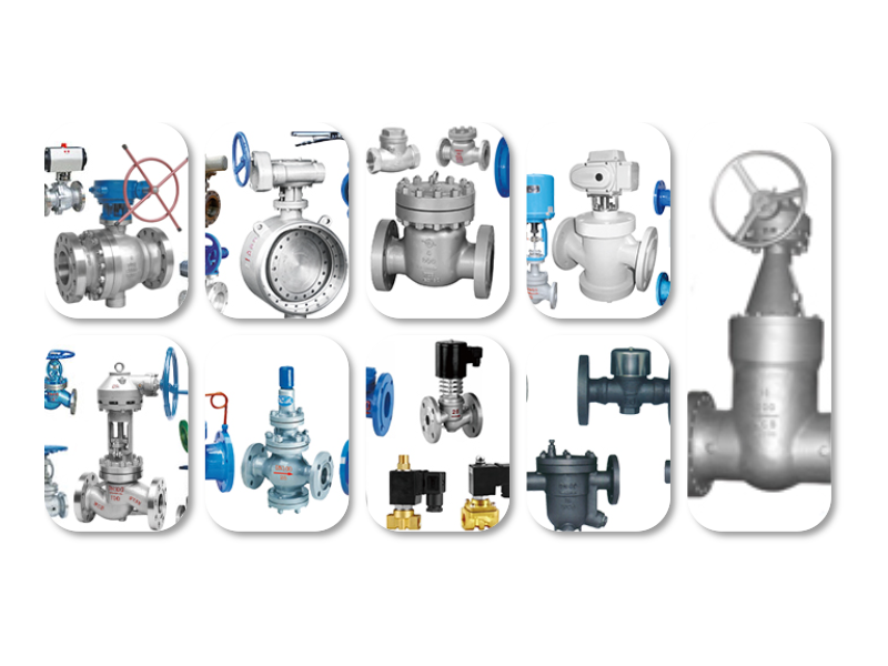
Valves are essential components in various industries, including oil and gas, water treatment, and chemical processing. They are used to control the flow of fluids, regulate pressure, and prevent backflow. The design and manufacturing of valves require precision and accuracy, which can be achieved through the use of Valve CAD drawings.
**The Importance of Valve CAD Drawings**
Valve CAD drawings serve several crucial purposes in the valve manufacturing process:
1. **Design Verification**: CAD drawings allow engineers to verify the design of the valve before manufacturing begins. This helps identify potential design flaws and make necessary adjustments before production.
2. **Communication**: CAD drawings serve as a common language between engineers, designers, and manufacturers. They ensure that everyone involved in the process has a clear understanding of the valve’s design and specifications.
3. **Manufacturing Efficiency**: By providing detailed information about the valve’s components and assembly process, CAD drawings help manufacturers optimize their production processes and reduce manufacturing time.
4. **Quality Control**: CAD drawings enable manufacturers to maintain consistent quality throughout the production process. By following the drawings, manufacturers can ensure that each valve meets the required specifications and standards.
**Components of Valve CAD Drawings**
Valve CAD drawings typically include the following components:
1. **General Information**: This section provides an overview of the valve, including its type, size, and material.
2. **Detail Drawings**: These drawings show the individual components of the valve, such as the body, bonnet, seat, and stem. They include dimensions, tolerances, and surface finishes.
3. **Assembly Drawings**: These drawings show how the individual components are assembled to form the complete valve. They include the sequence of assembly, fastener sizes, and torque specifications.
4. **Piping and Instrumentation Diagrams (P&IDs)**: P&IDs show the valve’s connection to other components in the system, such as pipes, valves, and instruments.
5. **Material Specifications**: This section lists the materials used in the valve’s construction, including grades, standards, and suppliers.
**How Valve CAD Drawings Contribute to Efficiency and Quality**
Valve CAD drawings contribute to the efficiency and quality of valve manufacturing in several ways:
1. **Reduced Errors**: By providing detailed and accurate information, CAD drawings help reduce errors during the manufacturing process.
2. **Improved Communication**: CAD drawings facilitate clear and concise communication between all parties involved in the valve manufacturing process.
3. **Streamlined Production**: CAD drawings allow manufacturers to optimize their production processes, reducing manufacturing time and costs.
4. **Enhanced Quality Control**: CAD drawings enable manufacturers to maintain consistent quality throughout the production process, ensuring that each valve meets the required specifications and standards.
**Conclusion**
Valve CAD drawings are an essential tool in the design and manufacturing of valves. They provide engineers and manufacturers with the necessary information to ensure the proper functioning and assembly of valves. By using Valve CAD drawings, manufacturers can improve efficiency, reduce errors, and maintain consistent quality throughout the production process.
Leave a Reply